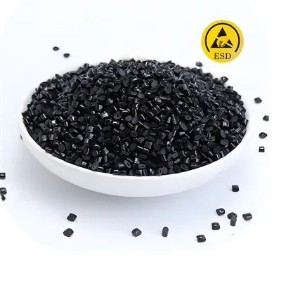

When specifying ESD-safe conductive modified plastics, many material engineers notice a consistent industry phenomenon: short-chopped carbon-fiber-filled conductive compounds mostly deliver stable surface resistivity within 10⁵-10⁹ Ω/sq static-dissipative range. It is difficult to reach very low conductive resistivity (below 10⁴ Ω/sq) with carbon-fiber-only formulations, while carbon-black-filled grades can achieve lower resistance more easily. This is not a product defect, but an inherent performance boundary caused by filler geometry, percolation network and processing conditions.
Conductive Mechanism of Carbon-fiber-filled Compounds
Conductive short-cut carbon fibers build 3-D conductive pathways inside insulating polymer matrix by physical contact, following percolation-threshold theory. Once filler loading exceeds critical threshold, fiber-to-fiber contacts form continuous conductive networks and switch material from insulator to static-dissipative or conductive status.
Carbon fiber is a high-aspect-ratio fibrous filler. It can establish conductive networks at relatively low loading while improving stiffness and mechanical strength. Meanwhile, it brings intrinsic processing restrictions that define its practical resistivity window.

Four Key Factors Limiting Resistivity of Carbon-fiber Conductive Plasticsa
Fiber breakage under twin-screw shearing damages conductive pathways During compounding and injection molding, intense screw shear cuts short carbon fibers into shorter segments. Shorter fibers reduce overlapping contact probability and weaken continuity of conductive networks. Simply raising carbon-fiber weight percentage cannot linearly push resistivity lower.
Carbon-fiber fillers are prone to agglomeration with narrow processing window Carbon-fiber fillers tend to agglomerate in polymer melt. - Low loading: good dispersion yet insufficient fiber contact, higher resistivity around 10⁸-10⁹ Ω/sq. - Excess loading: severe fiber agglomeration. Some zones become over-conductive while other areas remain insulating. Melt viscosity rises sharply, bringing poor flowability, bad surface finish and degraded mechanical performance.
For mass production, manufacturers keep carbon-fiber loading within a practical operating window, yielding stable resistivity in 10⁵-10⁹ Ω/sq, balancing ESD performance, processability and mechanical properties.
Contact resistance between overlapping carbon-fiber segments Conduction relies on physical point-to-point contact between carbon-fiber filaments, creating notable inter-fiber contact resistance. Compared with densely packed carbon-black particle networks, carbon-fiber systems retain higher overall contact resistance at similar loading. To get resistivity below 10⁴ Ω/sq, extremely high carbon-fiber loading is required, which sacrifices flow and impact performance and is rarely adopted for standard ESD structural parts.
Fiber orientation after molding causes electrical anisotropy During injection molding, carbon fibers align along melt flow direction. Reduced cross-direction fiber overlap leads to anisotropic electrical performance. Surface resistivity differs between flow and cross-flow directions, further limiting how low resistivity can go.
Comparison: Carbon-fiber vs Carbon-black Filled Conductive Plastics
表格
|
Item |
Carbon-fiber-filled conductive plastics |
Carbon-black-filled conductive plastics |
|
Typical stable surface resistivity |
10⁵-10⁹ Ω/sq (static-dissipative dominant) |
10³-10⁹ Ω/sq, wide tunable range |
|
Filler morphology |
Short-cut fibrous, high aspect ratio |
Nano-/micro-sized particles |
|
Processing challenges |
Fiber breakage, agglomeration, electrical anisotropy |
High viscosity at high loading, slough-off / bleed-out risk |
|
Core advantages |
Enhanced stiffness & strength, permanent ESD, low bleed-out risk |
Easier to achieve low resistivity, cost-effective |
|
Typical applications |
High-strength ESD structural parts, tooling trays |
ESD packaging, blow-molded conductive articles |
Hybrid dual-filler formulation (carbon fiber + carbon black) is widely adopted in industry: carbon-black particles fill gaps between carbon-fiber filaments to optimize conductive networks for balanced strength and conductivity.
Practical Selection Guidance for Engineers & Procurement
For standard ANSI/ESD S20.20 static-dissipative requirement (10⁶-10⁹ Ω/sq) plus structural strength: carbon-fiber modified plastic is an excellent option, delivering humidity-independent permanent ESD performance with low bleed-out risk.
If target resistivity below 10⁵ Ω/sq without high mechanical requirement: select carbon-black filled grades or carbon-fiber/carbon-black hybrid compounds.
Avoid blindly chasing ultra-low resistivity: excessively low resistance may trigger instantaneous discharge and harm sensitive electronic components. Always match resistivity grade to real-world application scenarios.
Perform physical part testing: injection or extrusion processes change fiber length and orientation. Final surface resistivity should be measured on finished components rather than relying solely on pellet datasheet values.
About Us
We provide custom-formulated conductive & antistatic modified compounds and masterbatches. Operating 20 production lines with monthly capacity 800-1000 tons, we supply carbon-fiber filled, carbon-black filled and hybrid-filler materials based on HDPE, POM, PEEK, PC-ABS and other engineering resins. We offer traceable quality-control and fast bulk-order replenishment for ESD-packaging and structural-component projects.